|
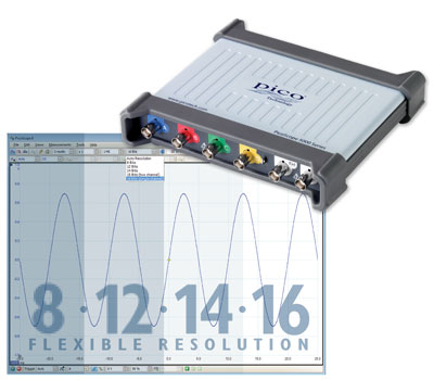
PicoScope 5000-serie Hardware configureerbare
verticale resolutie |
 Hoge
snelheid en hoge resolutie. Een doorbraak en ADC technologie, Hoge
snelheid en hoge resolutie. Een doorbraak en ADC technologie,
schakelt van 8 tot 16 bits in dezelfde oscilloscoop.
• Flexibele hardware resolutie, van 8 tot 16
Bits
• 200 Mhz analoge bandbreedte
• 1 GS real-time sampling
• 512
MS buffer geheugen
• 200 MS/s AWG
PicoScope: power, portability and versatility
Pico Technology continues to push the limits of PC
oscilloscope design. For the first time in an oscilloscope,
Pico Technology have used reconfigurable ADCs to offer a
choice of 8-bit to 16-bit resolutions in a single product.
 Flexible resolution Flexible resolution
Most digital
oscilloscopes gain their high sampling rates by interleaving
multiple 8-bit ADCs. Despite careful design, the
interleaving process introduces errors that always make the
dynamic performance worse than the performance of the
individual ADC cores.
The new PicoScope 5000 series
scopes have a significantly different architecture in which
multiple high-resolution ADCs can be applied to the input
channels in different time-interleaved and parallel
combinations to boost either the sampling rate or the
resolution.
In time-interleaved mode, the ADCs are
interleaved to provide 1 GS/s at 8 bits (see diagram).
Interleaving reduces the performance of the ADCs, but the
resulting (60 dB SFDR) is still much better than
oscilloscopes that interleave 8-bit ADCs. This mode can also
provide 500 MS/s at 12 bits resolution.
In parallel mode, multiple ADCs are sampled in phase on each
channel to increase the resolution and dynamic performance
(see diagram). Sampling in parallel with multiple ADCs and
combining the output reduces noise and also both the
integral and differential nonlinearity.
Using
parallel mode, resolution is increased to 14 bits at 125
MS/s per channel (>70 dB SFDR). If only two channels are
required then resolution can be increased to 15 bits, and in
single-channel mode all the ADCs are combined to give a 16
bit mode at 62.5 MS/s. The software gives the choice of
selecting the resolution or leaving the scope in “auto
resolution” mode where the optimum resolution is used for
the chosen settings.
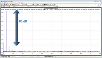
High
signal integrity
Most oscilloscopes are built
down to a price; ours are built up to a specification.
Careful front-end design and shielding reduces noise,
crosstalk and harmonic distortion. Over 20 years of high
resolution oscilloscope design experience leads to improved
pulse response and bandwidth flatness.
We are proud
of the dynamic performance of our products and publish these
specifications in detail. The result is simple: when you
probe a circuit, you can trust in the waveform you see on
the screen.
Portability
Pico Technology oscilloscopes are small, light and
portable. In 2-channel mode the 5000 series scopes can be
powered from USB only, making them ideal for the engineer on
the move. The external power supply is only needed when
operating more than 2 channels. The 5000 series
oscilloscopes are suitable for field use in many
applications, such as design, research, test, education,
service and repair.
|
Model |
PicoScope |
|
Bandwidth (–3 dB) |
60 MHz |
100 MHz |
200 MHz |
|
2 channel |
5242D |
5242D MSO |
5243D |
5243D MSO |
5244D |
5244D MSO |
|
4 channel |
5442D |
5442D MSO |
5443D |
5443D MSO |
5444D |
5444D MSO |
|
Oscilloscope - vertical |
|
Input type |
Single-ended, BNC connector |
|
Bandwidth (–3 dB) |
60 MHz |
100 MHz[1] |
200 MHz[1] |
|
Rise time (calculated) |
5.8 ns |
3.5 ns[1] |
1.75 ns[1] |
|
Bandwidth limiter |
20 MHz, selectable |
|
Vertical resolution[2] |
8, 12, 14, 15 or 16 bits |
|
LSB size[2](quantization
step size) |
8 bit mode: < 0.6% of input range
12 bit mode: < 0.04% of input range
14 bit mode: < 0.01% of input range
15 bit mode: < 0.005% of input range
16 bit mode: < 0.0025% of input range |
|
Enhanced vertical resolution |
Hardware resolution + 4 bits |
|
Input ranges |
±10 mV to ±20 V full scale, in 11 ranges |
|
Input sensitivity |
2 mV/div to 4 V/div (10 vertical divisions) |
|
Input coupling |
AC / DC |
|
Input characteristics |
1 MΩ ± 1% || 14 ±1 pF |
|
Gain accuracy |
12 to 16 bit modes: ±0.5% of signal ±1 LSB[3]
8 bit mode: ±2% of signal ±1 LSB[3] |
|
Offset accuracy |
±500 µV ±1% of full scale[3]
Offset accuracy can be improved by using the
“zero offset” function in PicoScope 6. |
|
Analog offset range (vertical position adjust) |
±250 mV (10, 20, 50, 100, 200 mV ranges),
±2.5 V (500 mV, 1 V, 2 V ranges),
±20 V (5, 10, 20 V ranges) |
|
Analog offset control accuracy |
±0.5% of offset setting, additional to basic DC
offset accuracy |
|
Overvoltage protection |
±100 V (DC + AC peak) |
[1] In 16-bit mode, bandwidth reduced to
60 MHz and rise time increased to 5.8 ns.
[2] On ±20 mV range, in 14 to 16-bit
modes, hardware resolution reduced by 1 bit. On ±10 mV
range, hardware resolution reduced by 1 bit in 12-bit mode,
2 bits in 14 to 16-bit modes.
[3] Between 15 and 30 °C after 1 hour
warm-up.
|
Vertical (digital channels) – D MSO models only |
|
Input channels |
16 channels (2 ports of 8 channels each) |
|
Input connector |
2.54 mm pitch, 10 x 2 way connector |
|
Maximum input frequency |
100 MHz (200 Mbit/s) |
|
Minimum detectable pulse width |
5 ns |
|
Input impedance |
200 kΩ ±2% || 8 pF ±2 pF |
|
Input dynamic range |
±20 V |
|
Threshold range |
±5 V |
|
Threshold grouping |
Two independent threshold controls. Port 0: D0
to D7, Port 1: D8 to D15 |
|
Threshold selection |
TTL, CMOS, ECL, PECL, user-defined |
|
Threshold accuracy |
< ±350 mV including hysteresis |
|
Threshold hysteresis |
< ±250 mV |
|
Minimum input voltage swing |
500 mV peak to peak |
|
Channel-to-channel skew |
2 ns, typical |
|
Minimum input slew rate |
10 V/µs |
|
Overvoltage protection |
±50 V (DC + AC peak) |
|
Horizontal |
Max. sampling rate
Any 1 channel
Any 2 channels
Any 3 or 4 channels
More than 4 channels |
8-bit mode
1 GS/s
500 MS/s
250 MS/s
125 MS/s |
12-bit mode
500 MS/s
250 MS/s
125 MS/s
62.5 MS/s |
14-bit mode
125 MS/s
125 MS/s
125 MS/s
62.5 MS/s |
15-bit mode[4]
125 MS/s
125 MS/s |
16-bit mode[4]
62.5 MS/s |
"Channel" means any analog channel or 8-bit
digital port
[4]Any number of 8-bit digital ports can
be used in 15-bit and 16-bit modes without
affecting the maximum sampling rate |
|
Maximum equivalent sampling rate (repetitive
signals; 8-bit mode only, ETS mode) |
2.5 GS/s |
5 GS/s |
10 GS/s |
|
Maximum sampling rate (continuous USB streaming
into PC memory)[5] |
USB3, using PicoScope 6: 15 to 20 MS/s
USB3, using PicoSDK: 125 MS/s (8-bit) or 62.5
MS/s (12 to 16 bit modes)
USB2, using PicoScope 6: 8 to 10 MS/s
USB2, using PicoSDK: ~30 MS/s (8-bit) or ~15
MS/s (12 to 16 bit modes) |
|
Timebase ranges (real time) |
1 ns/div to 5000 s/div in 39 ranges |
|
Fastest timebase (ETS) |
500 ps/div |
200 ps/div |
100 ps/div |
|
Buffer memory[6] (8-bit
mode) |
128 MS |
256 MS |
512 MS |
|
Buffer memory[6] (≥
12-bit mode) |
64 MS |
128 MS |
256 MS |
|
Buffer memory[7](continuous
streaming) |
100 MS in PicoScope software |
|
Waveform buffer (no. of segments) |
10 000 in PicoScope software |
|
Waveform buffer (no. of segments) when using
PicoSDK (8 bit mode) |
250 000 |
500 000 |
1 000 000 |
|
Waveform buffer (no. of segments) when using
PicoSDK (12 to 16 bit modes) |
125 000 |
250 000 |
500 000 |
|
Initial timebase accuracy |
±50 ppm (0.005%) |
±2 ppm (0.0002%) |
±2 ppm (0.0002%) |
|
Timebase drift |
±5 ppm/year |
±1 ppm/year |
±1 ppm/year |
|
Sample jitter |
3 ps RMS, typical |
|
ADC sampling |
Simultaneous on all enabled channels |
[5]Shared between enabled channels, PC dependent,
available sample rates vary by resolution.
[6]Shared between enabled channels.
[7]Driver buffering up to available PC memory when
using PicoSDK. No limit on duration of capture.
|
Dynamic performance (typical; analog channels) |
|
Crosstalk |
Better than 400:1 up to full bandwidth (equal
voltage ranges) |
|
Harmonic distortion |
8-bit mode: −60 dB at 100 kHz full scale input.
12-bit mode or higher: −70 dB at 100 kHz full
scale input
|
|
SFDR |
8 to 12-bit modes: 60 dB at 100 kHz full scale
input.
14 to
16-bit modes: 70 dB at 100 kHz full scale input. |
|
Noise (on most sensitive range) |
8-bit mode: 120 μV RMS
12-bit mode: 110 μV RMS
14-bit mode: 100 μV RMS
15-bit mode: 85 μV RMS
16-bit mode: 70 μV RMS |
|
Bandwidth flatness |
(+0.3 dB, –3 dB) from DC to full bandwidth |
|
Triggering (main specifications) |
|
Source |
Analog channels, plus: MSO models: Digital D0 to
D15. Other models: Ext trigger. |
|
Trigger modes |
None, auto, repeat, single, rapid (segmented
memory). |
|
Advanced trigger types (analog channels) |
Edge, window, pulse width, window pulse width,
dropout, window dropout, interval, runt, logic. |
|
Trigger types (analog channels, ETS) |
Rising or falling edge ETS trigger available on
ChA only, 8-bit mode only. |
|
Trigger sensitivity (analog channels) |
Digital triggering provides 1 LSB accuracy up to
full bandwidth of scope. |
|
Trigger sensitivity (analog channels, ETS) |
At full bandwidth: typical 10 mV peak to peak |
|
Trigger types (digital inputs) |
MSO models only: Edge, pulse width, dropout,
interval, logic, pattern, mixed signal. |
|
Maximum pre-trigger capture |
Up to 100% of capture size. |
|
Maximum post-trigger delay |
Zero to 4 billion samples, settable in 1 sample
steps (delay range on fastest timebase of 0 – 4
s in 1 ns steps) |
|
Trigger rearm time |
8-bit mode, typical: 1 μs on fastest timebase
8 to 12 bit modes: < 2 μs max on fastest
timebase
14
to 16 bit modes: < 3 μs max on fastest timebase |
|
Maximum trigger rate |
10 000 waveforms in a 10 ms burst, 8-bit mode |
|
External trigger input – not MSO models |
|
Connector type |
Front panel BNC |
|
Trigger types |
Edge, pulse width, dropout, interval, logic |
|
Input characteristics |
1 MΩ ± 1% || 14 pF ±1.5 pF |
|
Bandwidth |
60 MHz |
100 MHz |
200 MHz |
|
Threshold range |
±5 V |
|
Threshold range |
±5 V, DC coupled |
|
External trigger threshold accuracy |
±1% of full scale |
|
External trigger sensitivity |
200 mV peak to peak |
|
Coupling |
DC |
|
Overvoltage protection |
±100 V (DC + AC peak) |
|
Function generator |
|
Standard output signals |
Sine, square, triangle, DC voltage, ramp up,
ramp down, sinc, Gaussian, half-sine |
|
Pseudorandom output signals |
White noise, selectable amplitude and offset
within output voltage range.
Pseudorandom binary sequence (PRBS), selectable
high and low levels within output voltage range,
selectable bit rate up to 20 Mb/s |
|
Standard signal frequency |
0.025 Hz to 20 MHz |
|
Sweep modes |
Up, down, dual with selectable start / stop
frequencies and increments |
|
Triggering |
Can trigger a counted number of waveform cycles
or frequency sweeps (from 1 to 1 billion) from
the scope trigger, external trigger or from
software. Can also use the external trigger to
gate the signal generator output. |
|
Output frequency accuracy |
Oscilloscope timebase accuracy ± output
frequency resolution |
|
Output frequency resolution |
< 0.025 Hz |
|
Output voltage range |
±2 V |
|
Output voltage adjustments |
Signal amplitude and offset adjustable in approx
0.25 mV steps within overall ±2 V range |
|
Amplitude flatness |
< 1.5 dB to 20 MHz, typical |
|
DC accuracy |
±1% of full scale |
|
SFDR |
> 70 dB, 10 kHz full scale sine wave |
|
Output resistance |
50 Ω ±1% |
|
Connector type |
BNC(f) |
|
Overvoltage protection |
±20 V |
|
Arbitrary waveform generator |
|
AWG update rate |
200 MHz |
|
AWG buffer size |
32 kS |
|
AWG resolution |
14 bits (output step size approximately 0.25 mV) |
|
AWG bandwidth |
> 20 MHz |
|
AWG rise time (10% to 90%) |
< 10 ns (50 Ω load) |
Additional AWG specifications including sweep modes,
triggering, frequency accuracy and resolution, voltage
range, DC accuracy and output characteristics are as the
function generator
|
Probe compensation pin |
|
Output characteristics |
600 Ω |
|
Output frequency |
1 kHz |
|
Output level |
3 V peak to peak, typical |
|
Overvoltage protection |
10 V |
|
Spectrum analyzer |
|
Frequency range |
DC to 60 MHz |
DC to 100 MHz |
DC to 200 MHz |
|
Display modes |
Magnitude, average, peak hold |
|
Y axis |
Logarithmic (dbV, dBu, dBm, arbitrary dB) or
linear (volts) |
|
X axis |
Linear or logarithmic |
|
Windowing functions |
Rectangular, Gaussian, triangular, Blackman,
Blackman–Harris, Hamming, Hann, flat-top |
|
Number of FFT points |
Selectable from 128 to 1 million in powers of 2 |
|
Math channels |
|
Functions |
−x, x+y, x−y, x*y, x/y, x^y, sqrt, exp, ln, log,
abs, norm, sign, sin, cos, tan, arcsin, arccos,
arctan, sinh, cosh, tanh, delay, average,
frequency, derivative, integral, min, max, peak,
duty, highpass, lowpass, bandpass, bandstop |
|
Operands |
A, B, C, D (input channels), T (time), reference
waveforms, pi, D0−D15 (digital channels),
constants |
|
Automatic measurements |
|
Scope mode |
AC RMS, true RMS, frequency, cycle time, duty
cycle, DC average, falling rate, rising rate,
low pulse width, high pulse width, fall time,
rise time, minimum, maximum, peak to peak |
|
Spectrum mode |
Frequency at peak, amplitude at peak, average
amplitude at peak, total power, THD %, THD dB,
THD+N, SFDR, SINAD, SNR, IMD |
|
Statistics |
Minimum, maximum, average, standard deviation |
|
DeepMeasure™ |
|
Parameters |
Cycle number, cycle time, frequency, low pulse
width, high pulse width, duty cycle (high), duty
cycle (low), rise time, fall time, undershoot,
overshoot, max. voltage, min. voltage, voltage
peak to peak, start time, end time |
|
Serial decoding |
|
Protocols |
1-Wire, ARINC 429, CAN & CAN-FD, DCC, DMX512,
Ethernet 10Base-T and 100Base-TX, FlexRay, I²C,
I²S, LIN, PS/2, MODBUS, SENT, SPI, UART (RS-232
/ RS-422 / RS-485), USB 1.1 |
|
Mask limit testing |
|
Statistics |
Pass/fail, failure count, total count |
|
Mask creation |
User-drawn, table entry, auto-generated from
waveform or imported from file |
|
Display |
|
Interpolation |
Linear or sin(x)/x |
|
Persistence modes |
Digital color, analog intensity, custom, fast |
|
Software |
|
Windows software |
PicoScope for Windows
For Windows 7, 8 and 10 |
|
Languages |
Chinese (simplified), Chinese (traditional),
Czech, Danish, Dutch, English, Finnish, French,
German, Greek, Hungarian, Italian, Japanese,
Korean, Norwegian, Polish, Portuguese, Romanian,
Russian, Spanish, Swedish, Turkish |
|
General |
|
PC connectivity |
USB 3.0 SuperSpeed (USB 2.0 compatible) |
|
Power requirements |
2-channel models: powered from single USB 3.0
port
4-channel models: AC adaptor supplied. Can use 2
channels (plus MSO channels if fitted) powered
by USB 3.0 or charging port supplying 1.2 A. |
|
Dimensions |
190 x 170 x 40 mm including connectors |
|
Weight |
< 0.5 kg |
|
Temperature range |
Operating: 0 to 40 °C
15 to 30 °C for quoted accuracy after 1 hour
warm-up
Storage: –20 to +60 °C |
|
Humidity range |
Operating: 5 to 80 %RH non-condensing
Storage: 5 to 95 %RH non-condensing |
|
Environment |
Up to 2000 m altitude and EN61010 pollution
degree 2 |
|
Safety approvals |
Designed to EN 61010-1:2010 |
|
EMC approvals |
Tested to EN61326-1:2013 and FCC Part 15 Subpart
B |
|
Environmental approvals |
RoHS and WEEE compliant |
|
PC requirements |
Processor, memory and disk space: as required by
the operating system
Port(s): USB 3.0 or USB 2.0 |
|
Warranty |
5 years |
|